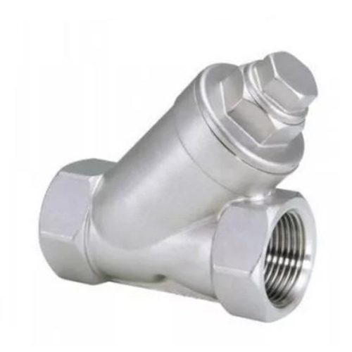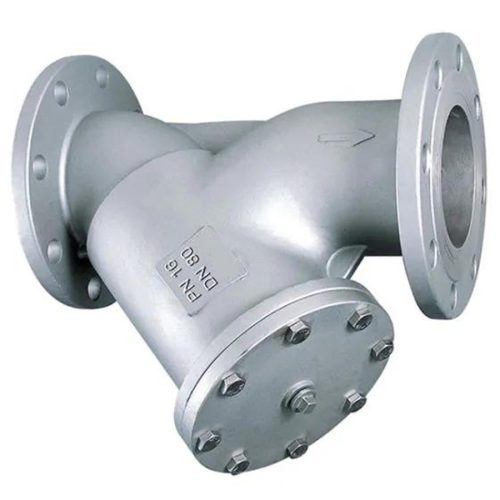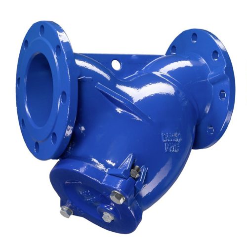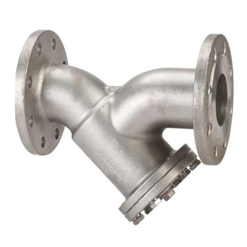

DN50 (2″) Class 150 ASTM A351 CF8M Y-Strainer OEM ODM Private Label YS027502
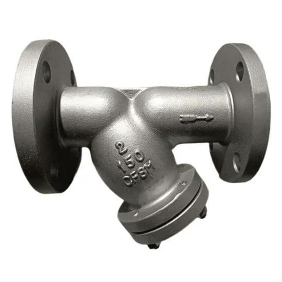
This 2″ (DN50) Class 150 Y-strainer meets ASME B16.34. The body is ASTM A351 CF8M cast stainless steel, with a 316 stainless steel screen (Mesh 40). End connections are RF flanged per ASME B16.5. The Y-type design has a built-in drain for easy cleaning. It filters out solids to protect pumps, meters, and valves. Suitable for water, gas, oil, and other general industrial fluids.
Product Attributes
| Valve Type | Y Strainer |
|---|---|
| Body Pattern | |
| Nominal Diameter (DN / NPS) | |
| Pressure Rating (PN / Class / JIS) | |
| Body Material | |
| Body Standard | |
| End Connection | |
| Connection Standard | |
| Face-to-Face Dimension | |
| Cover / Bonnet Type | |
| Cover / Bonnet Material | |
| Cover Seal / Gasket Material | |
| Screen / Basket Material | |
| Screen / Element Type | |
| Mesh Size | |
| Blowdown / Drain Connection | |
| Operation / Actuation | |
| Design Standard | |
| Suitable Media | |
| Working Temperature | |
| Application Industry | Chemical & Petrochemical, Food & Beverage, General Chemical, HVAC Systems, Industrial & Manufacturing, Oil & Gas, Water & Wastewater Treatment |
| Certifications | |
| OEM / Custom Service | Custom Actuator Mounting, Custom Body Material, Custom Coating / Surface Treatment, Custom Degreasing / Cleaning, Custom Design / Engineering, Custom Documentation, Custom End Connections, Custom Face-to-Face Length, Custom Logo / Branding, Custom Packaging, Custom Pressure Rating, Custom Seat & Packing Material, Full Product Traceability, ODM Service, OEM Service, Private Label |
Product Specifications
Product Usage
-
Protection of pumps, compressors, and turbines from particulate damage
-
Safeguarding control valves, flow meters, and instrumentation
-
Pipeline debris and scale removal during system startup
-
Cooling water and process water filtration
-
Steam and condensate systems (with appropriate materials)
-
Fuel oil and lube oil purification
-
Chemical and petrochemical process lines
-
HVAC and building services water systems
Construction Characteristics
-
Body material: ASTM A351 CF8M (cast stainless steel)
-
Screen material: SS 316 stainless steel
-
Screen mesh: Mesh 40 (standard)
-
Y-type (angled) body pattern for efficient particle collection
-
RF flanged end connections per ASME B16.5
-
Built-in drain connection for blowdown/cleaning
-
Bolted cover design for easy screen access and maintenance
-
Integral flange construction for long working life
-
Good flow efficiency with low pressure drop
-
Suitable media: Water, Gas, Oil, and other general fluids
-
Working temperature range: -46°C to 120°C (based on CF8M material)
Certification / Compliance Standards
-
Design and Manufacture: ASME B16.34
-
Face to Face Dimension: ASME B16.10
-
Flanged Connection: ASME B16.5 (RF)
-
Test and Inspection: API 598
-
Body Material: ASTM A351 CF8M
-
Body: ASTM A351 CF8M
-
Bonnet / Cover: ASTM A182 F316
-
Screen / Basket: SS 316
-
Gasket: 316 Stainless Steel + Graphite
-
Drain Connection: SS 316
-
Bolt: ASTM A193 B8M
-
Nut: ASTM A194 8M
| Class | NPS | L (mm) | O (mm) | W (mm) | R (mm) | Z-Φd (mm) | Tf (mm) | Weight (kg) |
|---|---|---|---|---|---|---|---|---|
| 150 | 2″ | 203 | 150 | 120.5 | 92 | 4-Φ19 | 14.3 | ~8.5 |
| 2-1/2″ | 216 | 178 | 139.7 | 105 | 4-Φ19 | 15.9 | ~18 | |
| 3″ | 241 | 190 | 152.4 | 127 | 4-Φ19 | 17.5 | ~21 | |
| 4″ | 292 | 229 | 190.5 | 157 | 8-Φ19 | 19.1 | ~32 | |
| 6″ | 406 | 279 | 241.3 | 216 | 8-Φ22 | 22.4 | ~48 | |
| 8″ | 495 | 343 | 298.5 | 270 | 8-Φ22 | 22.4 | ~105 | |
| 10″ | 622 | 406 | 362.0 | 324 | 12-Φ25 | 25.4 | ~169 | |
| 12″ | 699 | 483 | 431.8 | 381 | 12-Φ25 | 28.4 | ~215 | |
| 300 | 2″ | 248 | 165 | 127.0 | 92 | 8-Φ19 | 17.5 | ~12 |
| 2-1/2″ | 273 | 190 | 149.2 | 105 | 8-Φ22 | 20.6 | ~15 | |
| 3″ | 319 | 210 | 168.3 | 127 | 8-Φ22 | 22.4 | ~28 | |
| 4″ | 372 | 254 | 200.0 | 157 | 8-Φ22 | 25.4 | ~45 | |
| 6″ | 502 | 318 | 269.9 | 216 | 12-Φ22 | 28.4 | ~87 | |
| 8″ | 635 | 381 | 330.2 | 270 | 12-Φ25 | 31.8 | ~171 | |
| 10″ | 740 | 445 | 387.4 | 324 | 16-Φ28 | 35.1 | ~279 | |
| 12″ | 856 | 521 | 450.8 | 381 | 16-Φ28 | 38.1 | ~375 |
Notes:
-
L = Face-to-face length (end-to-end) per ASME B16.10.
-
O = Flange outer diameter.
-
W = Flange bolt circle diameter.
-
R = Flange hub diameter.
-
Z-Φd = Number of bolt holes and hole diameter.
-
Tf = Flange thickness.
-
Weight = Approximate unit weight.
-
Flange dimensions (O, W, R, Tf, Z-Φd) are based on ASME B16.5.
For exact dimensions and weights, especially for non-standard sizes, please contact us for more details.
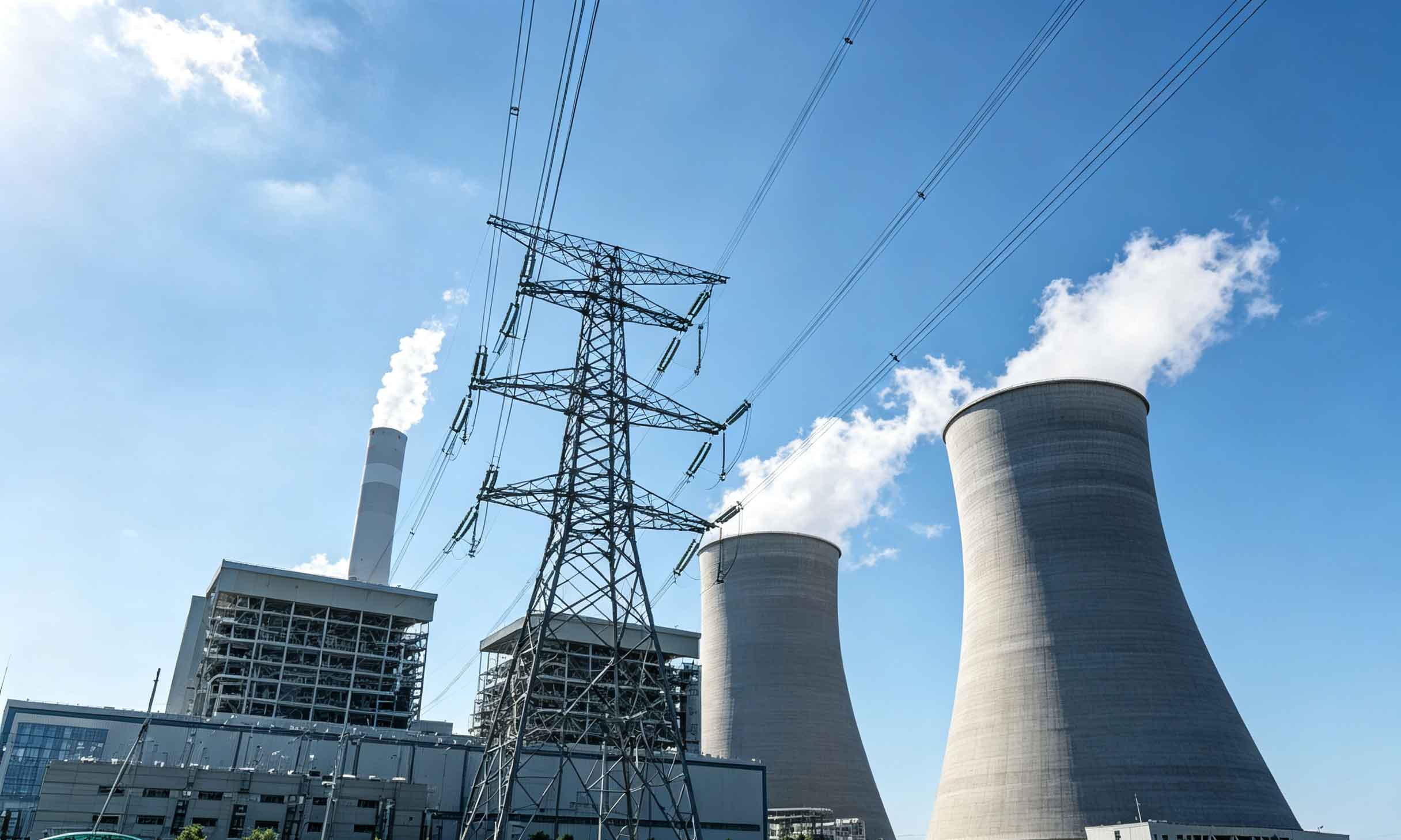
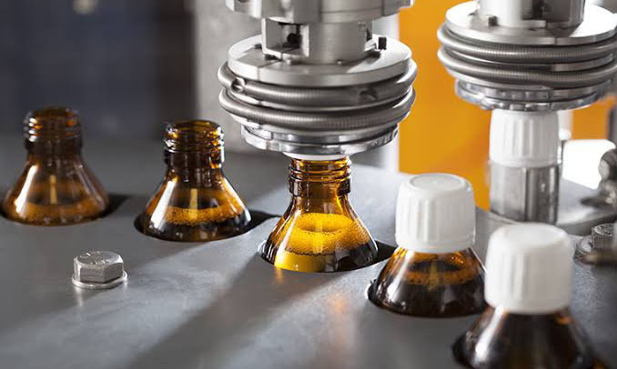
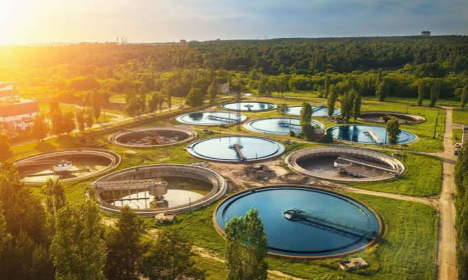
Industrial Applications

Why Choose BallValve Technology’s ASTM A351 CF8M Y-Strainers?
1) CE (2014/68/EU), UKCA, API, ASME, ISO 9001 certified. Full compliance with global pressure equipment and quality management standards – no regional restrictions, no documentation gaps.
2) Corrosion-resistant CF8M stainless steel construction. The ASTM A351 CF8M body provides excellent resistance to corrosion and pitting, ensuring long service life in demanding environments including chemical, petrochemical, and marine applications.
3) SS 316 screen for durability and reliability. The 316 stainless steel screen offers superior corrosion and wear resistance compared to standard carbon steel screens, maintaining filtration efficiency over extended periods.
4) 40 Mesh screen with built-in drain for easy maintenance. The standard 40 Mesh screen provides effective particle removal, while the built-in drain connection allows for blowdown cleaning without disassembling the strainer – reducing downtime and maintenance costs.
5) Y-type design for low pressure drop. The Y-pattern body design minimizes flow resistance while providing efficient particle collection, ensuring system performance is maintained.
6) RF flanged ends for secure installation. RF flanged connections per ASME B16.5 ensure a reliable, leak-tight joint and compatibility with standard piping systems.
7) Strict testing standards. You will receive test certificates of each Y-strainer issued by our laboratory or any third‑party institution that you have designated – hydrostatic shell and leakage tests fully documented per API 598.
8) Ten years of field wear data back every design margin. When you order a strainer, you receive an anonymized summary of identical or similar service duty (fluid, temperature, cycle frequency) from our field archives, including observed screen wear patterns, blowdown intervals, and maintenance recommendations.
9) Documentation is not an extra – it’s a serial number’s companion. Enter your strainer’s serial number on our portal: you get EN 10204 3.1 mill certificates, NDE reports, material verification, and the original assembly log. No separate request form, no waiting.
10) Performance witness test is your right, not a premium. Any strainer order includes one free witness test (your inspector or a third party) at our facility, with a 48‑hour notice. Witness includes hydrostatic shell test, leakage test, and screen integrity verification. No “witness fee”, no minimum quantity.
Frequently Asked Questions
Cleaning frequency depends on media cleanliness, mesh size, and flow rate. Monitor pressure drop — clean when it increases by 50% from the clean reading (or exceeds 0.5–0.7 bar). Clean gas lines may need annual cleaning; dirty water may need weekly.
Screen lifespan (typically 1–5 years) is affected by abrasion, corrosion, and physical damage during cleaning. Keep a spare screen to minimize downtime.
Yes. Our Y-Strainers are designed per ASME B16.34 and tested per API 598. Cast iron bodies comply with ASME B16.1. End connections follow ASME B16.5, B16.25, or B16.11. Potable water models feature NSF/ANSI 61 & 372 certification. Material test certificates (EN 10204 3.1/3.2) are available upon request.
Y-Strainers are passive devices and do not have actuator mounting interfaces for standard operation. For automated blowdown, we can supply a mounting pad for a ball valve actuator on the blowdown port — this is a custom option. Please contact us for specific requirements.
Y-Strainers don’t have “full-port” designs like ball valves. Flow restriction depends on:
-
Screen open area ratio (OAR): Typically 2:1 to 3:1 for Y-Strainers.
-
Mesh size: Finer mesh increases pressure drop.
Higher OAR = lower pressure drop and longer cleaning intervals. For critical low-pressure-drop applications, consider a larger strainer or basket strainer.
Yes, with correct material selection:
-
Steam: WCB with graphite seals handles up to 425°C; chrome-moly for higher temperatures.
-
Air: Carbon steel is typically sufficient.
-
Acid: Requires 316SS (CF8M), alloys (Hastelloy, MONEL), or PTFE-lined bodies. Screen material must match the acid type.
Always verify the pressure-temperature rating for your specific media.
-
Installation: Install with screen pointing downward in horizontal lines. Match flow arrow direction. Do not overtighten bolts.
-
Maintenance: Depressurize before opening cover. Replace gasket if damaged. After reassembly, perform a low-pressure leak test.
-
Torque: Use a calibrated wrench and star pattern. Typical torque: 50–150 N·m depending on bolt size.
The choice depends on the size of particles you need to capture. As a general guideline:
-
10–20 Mesh (≈841–2000 µm): For coarse straining, such as removing weld slag, rust, or large debris from new pipelines.
-
40–60 Mesh (≈250–400 µm): For general protection of pumps, control valves, and meters.
-
80–100 Mesh (≈149–177 µm): For fine straining, such as protecting spray nozzles or steam traps.
-
Perforated plates (1/32″–1/4″): Used when strength is more important than fine filtration.
If you’re unsure, we recommend starting with a 20–40 mesh for most liquid applications. We also offer custom mesh sizes upon request.
Our Y-Strainers are available in sizes from ½” (DN15) to 24″ (DN600), with pressure ratings ranging from Class 125 to Class 2500 (PN10 to PN420). The specific rating depends on the body material and connection type. For example, cast iron bodies typically follow Class 125/250 per ASME B16.1, while steel bodies follow Class 150/300/600 per ASME B16.5 and B16.34. Please refer to our product datasheets for detailed specifications by model.
| Stage | Procedure | Description |
|---|---|---|
| Before Production | PMI (Positive Material Identification) test | Raw material verification |
| In-Production | Dimensional checks | At critical machining stages |
| Post-Production | High-pressure hydrostatic shell test (1.5× rated pressure) Low-pressure air seat test (0.6 MPa) to verify shut-off Optional tests: helium leak test (ISO 15848), fire-safe test, or cryogenic test | Final assembly testing |
| Quality Inspection | Marking verification, coating/painting thickness measurement, and preparation of traceable test reports | Visual & documentary check |
All test records are archived for a minimum of 10 years and can be provided with each shipment. Or you can specify any third-party test institutions.
Our manufacturing facility is certified to ISO 9001:2015 for design, production, and after-sales service of industrial valves. Additionally, we hold ISO 14001:2015 (environmental management) and ISO 45001:2018 (occupational health and safety). All our ball valves for the European market comply with PED 2014/68/EU, and we can supply valves with ATEX certification for explosive atmospheres upon request. Our quality system is audited annually by third-party notified bodies.
Absolutely. For standard ball valves, we can offer off-the-shelf samples of common sizes (1/2″ to 4″) at a discounted price, with a refundable deposit that can be credited toward a future bulk order. For custom or larger sizes, we accept small trial orders (as few as 2–5 pieces) after a non-recurring engineering (NRE) fee is agreed. The NRE fee will be waived once the customer proceeds to a production order of 50 pieces or more.
We offer flexible payment terms based on order value and customer history. For standard orders: 30% deposit by T/T (wire transfer) with 70% balance before shipping. For larger or repeat customers, we can consider 20% deposit + 80% balance payment.
- For standard models, the minimum order quantity (MOQ) is usually 100 pieces per size. For sizes that are in stock, it takes 3 to 5 business days to ship after you place your order. Our usual lead time for making standard catalog valves that aren’t in stock is 15 to 25 business days after we get your order and approve the drawing.
- Custom models (with special materials, pressure classes, actuator mounting, custom logos, etc.): The minimum order quantity (MOQ) varies, so please get in touch with our sales team for a full quote. The lead time is usually 15 to 45 days, depending on how complicated the process is. Also, we offer a mixed-model consolidation service for distributors to help them deal with their inventory problems.
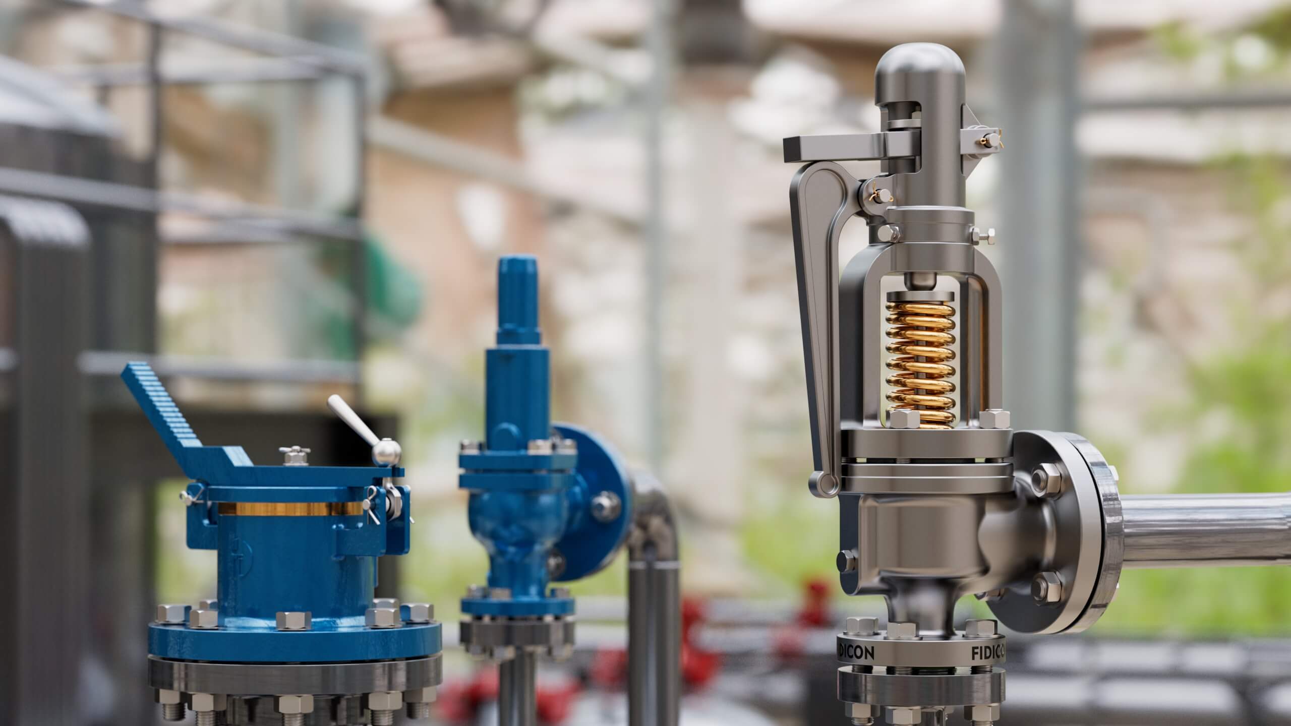
Looking for A Reliable Industrial Valve Manufacturer?
Our factory is equipped with a complete set of production facilities (three-axis, four-axis, and five-axis CNC machining centers, large vertical lathes, special process processing equipment, as well as fully automatic welding and sealing surface grinding equipment, etc.) and a testing laboratory, and implements a strict quality management system that has obtained ISO 9001 certification.
If you choose to cooperate with us, we will provide a complete set of certifications for each batch of valves: API 6D, API 600, API 607, CE/PED, TSG, ISO 15848-1 or other industry access certifications for specific fields. If you require us to provide testing and quality control, we will carry out non-destructive testing (NDT), material spectroscopy analysis, high-pressure gas tests, low-pressure airtight tests, torque tests, life cycle tests, and so on.
Each of our valves has a unique furnace batch number and serial number, which can be traced back to the raw material composition and assembly records. We also offer OEM/ODM services, and can customize special valves (design, materials, diameter, tolerance…) that meet the requirements of specific application scenarios for your special projects.
Leave An Inquiry
Please submit your inquiry via the form below or email [email protected]; Our team guarantees a response within 24 hours.